When comparing strain values obtained from DIC to analytical results or to strain results obtained from other measurement methods, it's important to select the strain tensor which matches your expected values. At low strains, many of these tensors will give very similar results, but at larger strains they can diverge and selecting the wrong tensor can give unexpected results.
The tensor can be selected either at run-time - in the Postprocessing tab of the Run dialog - or in the strain calculation dialog. Some of the more commonly used tensors are:
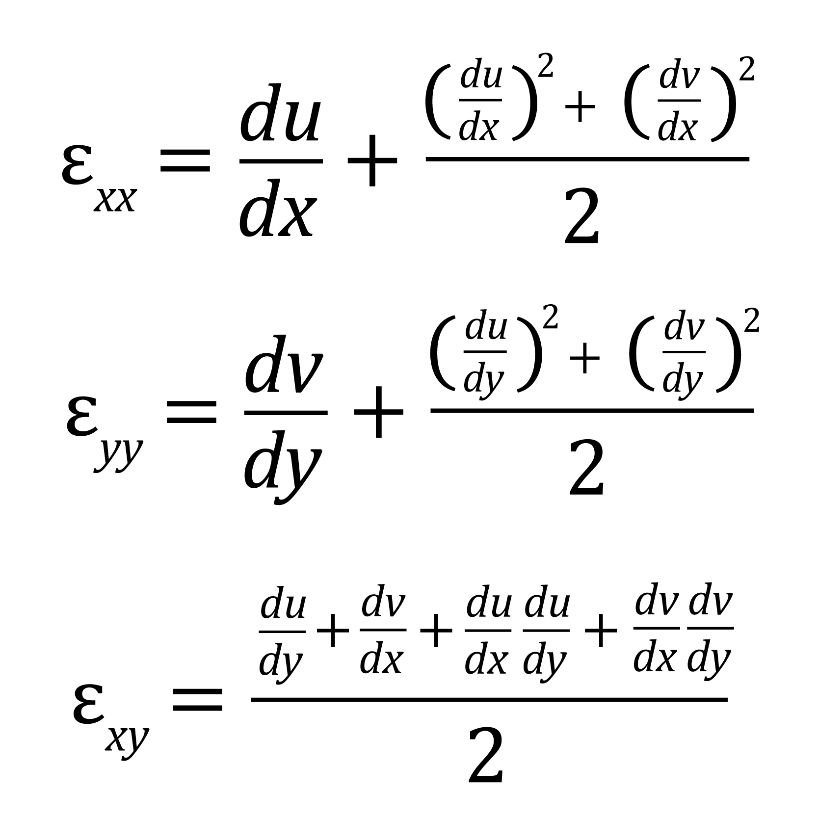
- Lagrange: this is the default tensor. The Lagrangian finite strain tensor, also known as the Green-Lagrangian strain tensor, is a finite strain measure which includes higher order displacement terms; it defines gradients in terms of the original configuration. This measure is commonly used for materials undergoing large strains such as elastomers. Please note that at large strains, the Lagrangian strain can become much larger than the extension or engineering strain due to the higher order term. The Lagrangian strain formulations are as follows:
- Engineering: In order to avoid non-sensical strains due to rigid body rotations, the engineering strain is not computed directly from the derivatives of the displacement, i.e., To make the strains insensitive to arbitrary rigid-body motion, the engineering strains are computed from the Lagrange strain tensor in the following manner:

- Hencky (Logarithmic): The Hencky strain, also known as true, natural, or logarithmic strain, is an incremental strain measure.
- Euler-Almansi: This is a finite strain tensor which is reference to the deformed strain configuration.
All of these tensors will be given in terms of exx (the strain along the X axis), eyy (strain in the Y axis), exy (the shear strain tensor - note that this is equal to half the engineering shear strain, unless Engineering is selected in which case the engineering shear strain is given), as well as e1 (major strain), e2 (minor strain), and gamma (the major strain angle - the angle, in radians, between the +x axis and the major strain axis).
Shear strain sign convention
To visualize what shear strain sign corresponds to what angle change, we can start from the (engineering) shear definition gamma = du/dy + dv/dx. Assume we have an initially square material element and deform it such that the top and bottom edges move horizontally, i.e., dv/dx = dv/dy = 0. This turns the square into a parallelogram. In a right-hand coordinate system, where x points right, y points up and z towards us, the shear strain is positive if the top edge moves to the right and negative if the top edge moves to the left relative to the bottom edge.
Von Mises strain calculation
Because VIC-3D only calculates surface strains, the built-in Von Mises calculation uses a principal plane strain formulation; other formulations would require assumptions/inferences about the through-thickness behavior of the material. The equation is as follows:

Tresca calculation
The Tresca calculation also uses a plane strain constraint.
- Where ε1 and ε2 have opposite signs, the result is (ε1-ε2)/2.
- Where they have the same sign, we use εmax/2 where εmax is the higher magnitude strain component.
Additional formulations can be easily composed using the function editor.
Strain axes
For many setups, the X axis or Y axis will naturally align with the axial or transverse strain axis, but if alignment is critical, you should either use major strains, or specify a coordinate system (for instance, force the Y-axis to the longitudinal axis of your specimen). Note that applying a coordinate transform will not transform associated strains - you will be prompted of this when applying transforms; re-calculate strain to get strains in your new coordinate system.
For some additional information about deformation descriptors and tensors, see the respective Wikipedia articles:
Micah Simonsen
Comments